April 8th, 2001
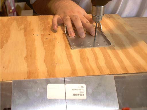
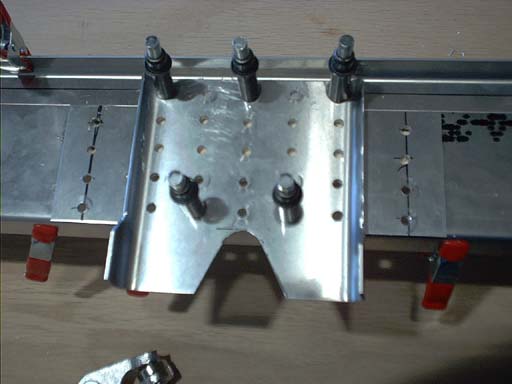
Work continues on the rear spar of the Stabilizer. Next up, I predrill the matrix of 25 rivets for the rear attachment plate. The matrix is a 5 x 5 grid, with the top row going through the plate, the spar web and the top doubler, the middle three rows going through the plate, a .016 spacer and the spar web, and the bottom row going through the plate, the spacer, the spar web and the lower doubler. Lots 'o' drillin'. Thanks Don Honabach for the template I found on his site for the matrix. Made life much easier.
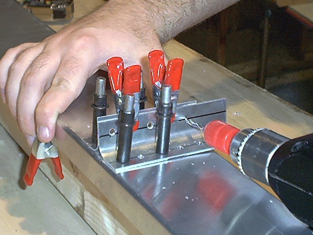
I found the best results were to center punch the plate through the paper matrix, then pre-drill the part. Be VERY careful when center-punching aluminum parts that you support the back of the plate on something like an anvil. Flat, hard steel. 6061 aluminum doesn't stand a chance against hardened tool steel and will deform if you try to center-punch it on a workbench or something equally soft.
Once the part was pre-drilled, I lined up the plate, the spacer and the spar and drilled through. This is ALOT of material for the drill to penetrate and will take time. Don't force the drill into the work, and be sure the bit doesn't load up with shavings.
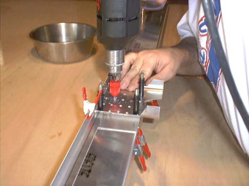
You'll notice the red device on the bit. That's a drill stop, and is an absolute requirement when drilling, especially when you get around to drilling the skins. Remember, hardened tool steel vs. aluminum = cashed part. I'm drilling out these parts with the #20 (bigger) bit. This was probably not a great idea, as I managed to mess up one of the holes as the part shifted. Had I drilled with the smaller bit first, it would have probably still been small enough to not matter. As it is, I have an oblong hole in the lower spar doubler in the lower right hand corner. This hole will clearly not retain a full strength bond when riveted. What's worse, it's Sun 'n' fun time, which means that there's no one at the factory to help me out. Hopefully the folks on the mailing list will have an idea. I'm thinking if I drill out another hole between the two bottom holes (5mm from each hole) it will cover the strength lost in the bogus hole. Luckily, I don't have to make that decision yet.
With this work done, the work with the rear spar is complete for now. We move now onto the front stabilizer spar. This part too gets a pair of doublers to compliment the inside corners...
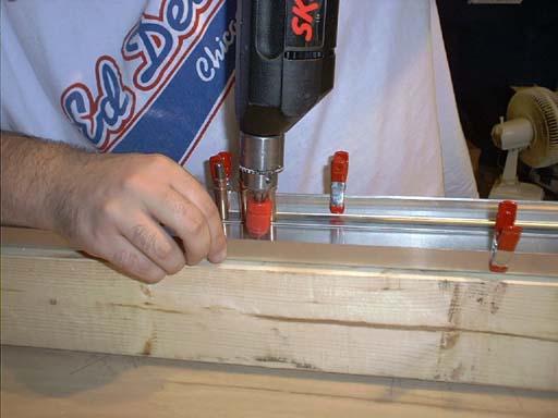
Once the doublers are in place, we have to determine the spacing for the front stabilizer attachment brackets. These work much like the rear plate, in that they protrude below the stabilizer and will eventually attach the stabilizer to the fuselage longerons. To get the proper spacing, we had to fashion a "template" of plywood that was perfectly square and, we thought according to the directions, 214mm wide. More on this later. To make this part, you either need a mitre box, or a radial arm saw. Luckily, we had an arm saw, and managed to knock the part out in short order. Had it not been for that tool, we'd have been done for the day, as the rest of the day would have been spent sawing and sanding this template.
Once we centered this block of wood to the spar and squared it off, we had to attach the bracket doublers along side the template, drill and cleco it in place. We then removed the template and affixed the actual brackets against the doublers and drilled/clecoed into place. We then went to the plans to verify our work and figure out if we had to cleco these two parts to one another.
Then we noticed that the drawing stated the template to be 219mm wide. This after we just drilled a bunch of holes 214 mm apart from each other. The difference of 2.5mm wider on each side does not give sufficient distance between the existing holes and the new holes to give appropriate strength, so they're going to stay at 214mm. We will have to add shims to fill the space between the longerons and the stabilizer bracket when it comes time to attach the two. We're apparently also not the first to make this mistake, and it's not a show-stopper. It was, however, dumb, as the supplemental manual we got the bogus measurements off of plainly state that in the event of discrepencies between that text and the plans, go with the information on the plans. At least we learned this lesson and it didn't cost me a part.
According to the drawings (which I now cross reference. Twice.) the two parts are riveted to each other, so I drill the parts and cleco them together. This seems to make sense anyway, even if I'm not supposed to.