April 7th, 2001
Fun with shop perparation, part deux.
Okay, enough of that fun. We basically moved stuff. And swept. The floor was very dirty. It still is, but this isn't a plastic airplane, so I'm not entirely concerned. Yet.
The landmark first part assembly took place today. I'm sure I'll look back on this in 20 years when I finish this project and re-read this. That is if the Internet hasn't imploded into some black hole centered in Redmond, WA or something. But I digress...
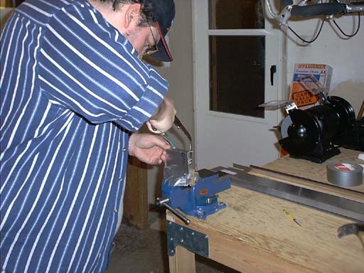
Anyway, went to work on the Horizontal Stabilizer. More specifically the rear spar assembly. Mike is working on the rear attachment plate. This plate is a hefty .062 plate that effectively attaches the rear of the stabilizer to the fuselage of the aircraft. It will eventually be held in place by 25 A5 type rivets.
Meanwhile, I went to work on the rear spar proper. After marking the centerline on all parts, I lined up the upper channel spar doubler inside the rear spar channel, drilled and clecoed into place.
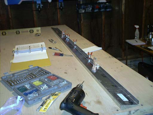
I then turned the spar over and affixed the lower spar double in the same fashion.
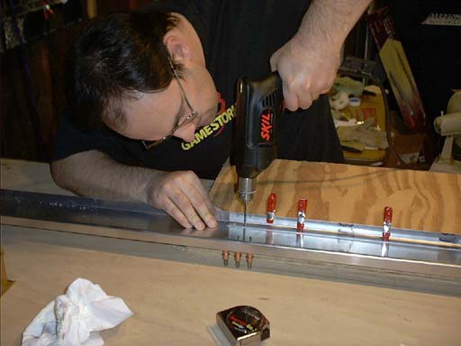
You'll notice that neither of us are wearing safety glasses. Bad habit to get into. That drill does sling some metal chunks around every once in a while. We're trying to get into the habit of wearing them. It's tough to fly when you're blind.
The trimmed rear attachment plate is shown in the picture below. The tall part of the attachment will protrude below the stabilizer and affix to the longerons in the rear fuselage.
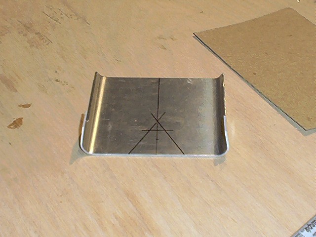
Let me explain those funky markings on the plate. The directions call for a U shaped cut in the base of the plate to clear the control cable going to the lower horn of the elevator. The directions also call for a 12mm radius "arc" apexing at the top of this (where the cross hatch of the A is). We didn't have a 12mm drill bit, so we had to get creative. The base of the opening is to be 40mm across, sweeping up into the 12mm radius. We initially thought about just "eyeballing" this, but then it struck us that a nickel would be about the right size. I would recommend using this technique, but with a 22mm washer to get the exact size. Ours worked out quite nicely though, and we'd been to 5 hardware stores by this point already, so going back out again was right at the bottom of the list...